




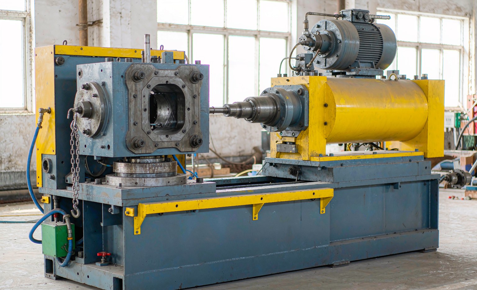
When buyers ask for “tight tolerance” injection molded parts, the conversation usually stalls because tolerance is not a single number — it is a function of the material, the mold, and how consistently the process is run. This guide explains what is realistically achievable under the international standard ISO 20457, why material shrinkage drives almost everything, and how to specify dimensions a molder can actually hit without a costly tool re-cut.
The core insight is that a molded dimension is the cavity size plus or minus a shrinkage that is never perfectly constant. Precision therefore comes from controlling shrinkage, not from demanding an arbitrarily small number.
What “tolerance” means in injection molding
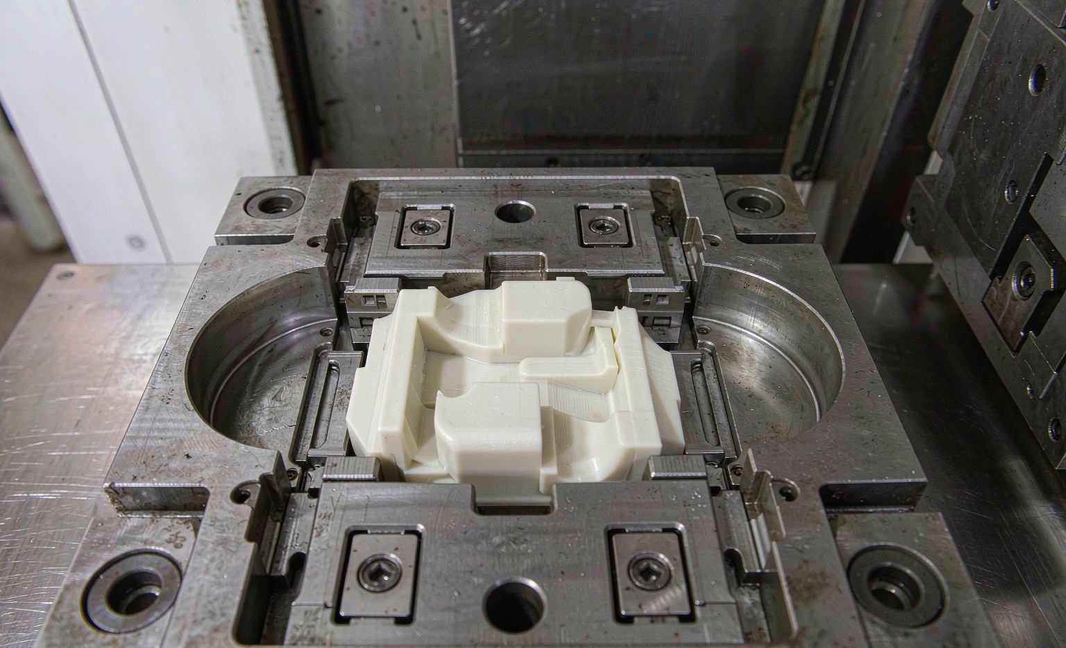
A tolerance is the permitted deviation from a nominal dimension, e.g. 50.00 ±0.20 mm. Unlike machining, a molded part is formed by molten plastic shrinking inside a steel cavity, so the final size depends on how much the polymer contracts as it cools. That contraction is never perfectly constant, which is why molded tolerances are wider than machined ones and are always quoted as a band rather than a target point.
A drawing that calls a molded feature to a machining-style ±0.05 mm will either be unmakeable or will quietly fail audit on every tenth part. The skill is to spend the tight tolerance only where the function needs it.
The reference standard: ISO 20457
ISO 20457:2018 — Plastics: Injection moulding of moulded parts — Tolerances and recommended values is the current international reference for molding tolerances. It defines several tolerance grades whose width grows with the nominal dimension. Representative values for unfilled thermoplastics:
| Nominal size (mm) | Fine | Medium | Coarse | Very coarse |
|---|---|---|---|---|
| 0 – 10 | 0.05 | 0.10 | 0.20 | 0.40 |
| 10 – 50 | 0.08 | 0.16 | 0.32 | 0.64 |
| 50 – 100 | 0.12 | 0.24 | 0.48 | 0.96 |
| 100 – 200 | 0.18 | 0.36 | 0.72 | 1.44 |
Values in millimetres; representative of ISO 20457 general tolerance tables for unfilled grades. Filled and glass-reinforced grades need wider bands.
Why shrinkage decides your tolerance
| Polymer | Typical mold shrinkage |
|---|---|
| Polypropylene (PP) | 1.0 – 2.5 % |
| HDPE | 1.5 – 3.0 % |
| ABS | 0.4 – 0.9 % |
| Polycarbonate (PC) | 0.5 – 0.8 % |
| POM (acetal) | 1.8 – 3.5 % |
| PA6 / PA66 (nylon) | 0.8 – 2.2 % |
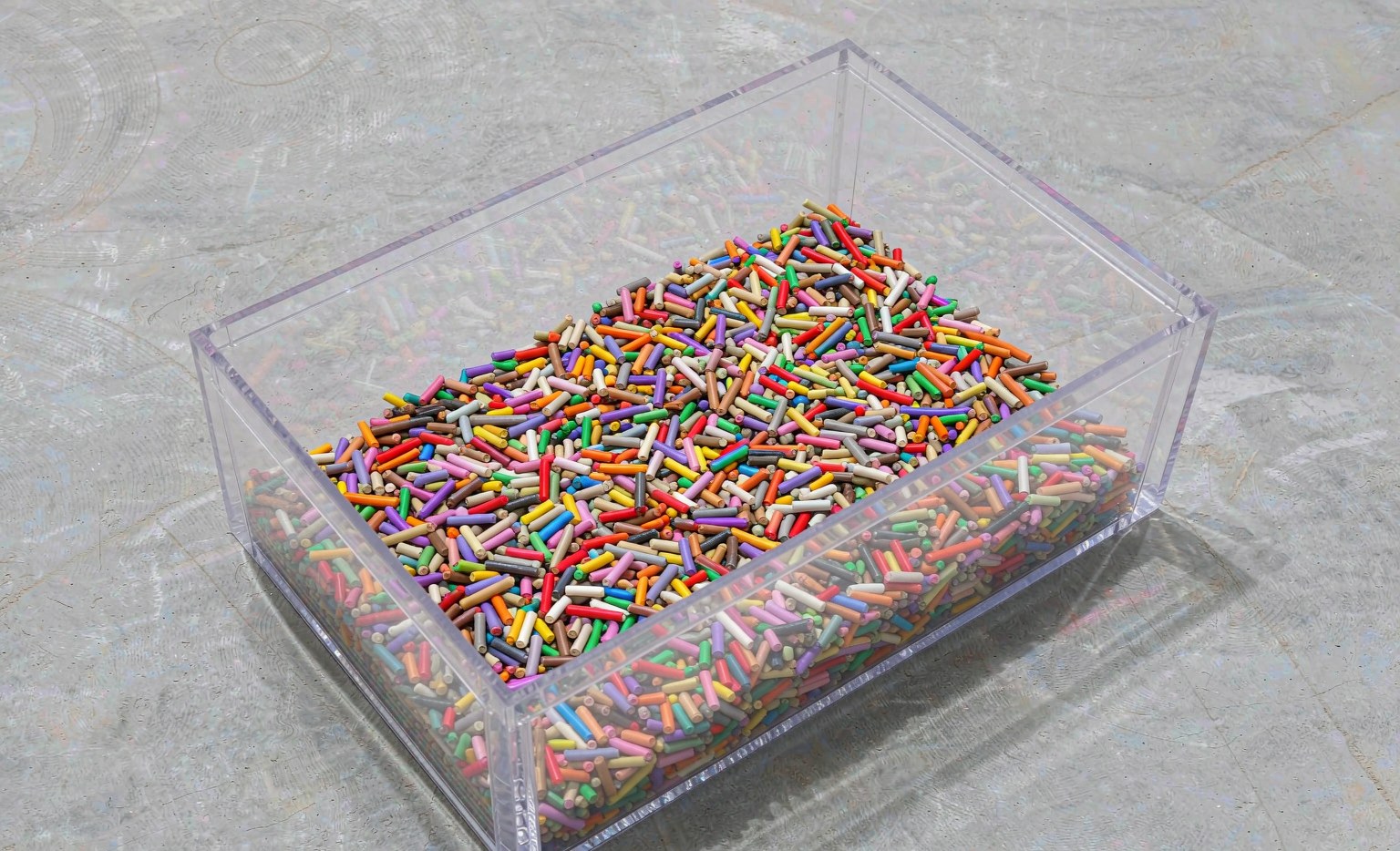
A 2 % shrink on a 100 mm dimension means roughly 2 mm of total contraction — so holding that feature to ±0.1 mm requires the process, and the material batch, to be extremely stable. This is why the resin is chosen before the tolerance is quoted.
Process factors that move dimensions
- Holding pressure & time — the biggest controllable lever; low pack pressure increases sink and shrink.
- Melt and mold temperature — higher mold temperature often raises shrinkage slightly but improves reproducibility.
- Gate location & size — distant gates cause fill-pressure gradients that show up as dimensional variation.
- Post-molding shrinkage — especially nylon (PA), which keeps absorbing moisture and changing size for days.
How to specify tolerances that get met

- Tolerate only the features that matter (fit, sealing, assembly) — over-specifying raises cost with no benefit.
- Quote an ISO 20457 grade rather than an arbitrary number, so the molder can choose tooling and process accordingly.
- For hygroscopic materials like PA, define the conditioning state (dry vs conditioned) the tolerance applies to.
- Validate with a first-article inspection (FAI) and a short production run before locking the print.
When tight tolerance is worth it
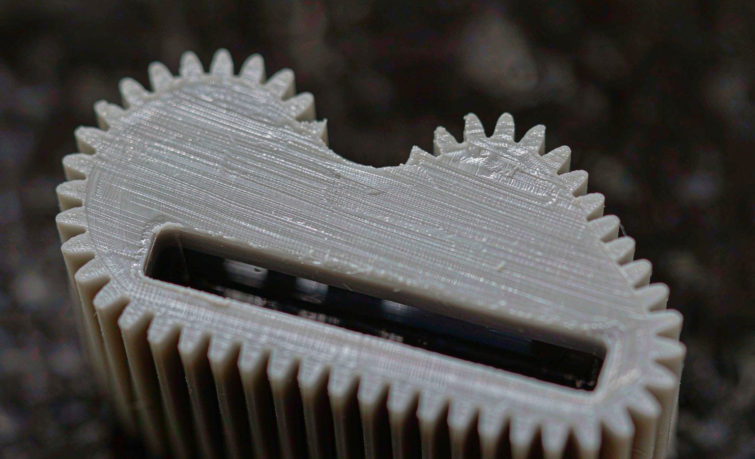
Use tight (fine) grades for gears, threaded closures, snap-fit features and medical/automotive interfaces. For non-critical housings and covers, medium or coarse grades are cheaper and faster to mold consistently.
Matching the tolerance to the function is the single biggest cost lever in any molding program, and specifying against a real standard keeps the molder and the buyer speaking the same language from the first tooling quote.
FAQ
Can any molded part hit ±0.05 mm? Only small features in stable materials with a fine grade; larger dimensions need correspondingly wider bands.
How do I check a molder can hold the tolerance? Ask for a process capability study (Cpk) from a first-article run before volume.
Does draft angle affect tolerance? Yes — draft and shrinkage compensation are designed into the cavity; tight tolerance near a drafted wall is harder to hold.
Why does the same mold drift over time? Tool wear and batch-to-batch shrinkage variation; re-validate the process window periodically.
Should I specify min or max material? Molded parts should list nominal plus tolerance; min/max-only callouts ignore shrinkage direction.
Is tighter tolerance always available at a price? Only to a point — past the material’s stability floor, no tooling budget fixes it.
Inspection and capability
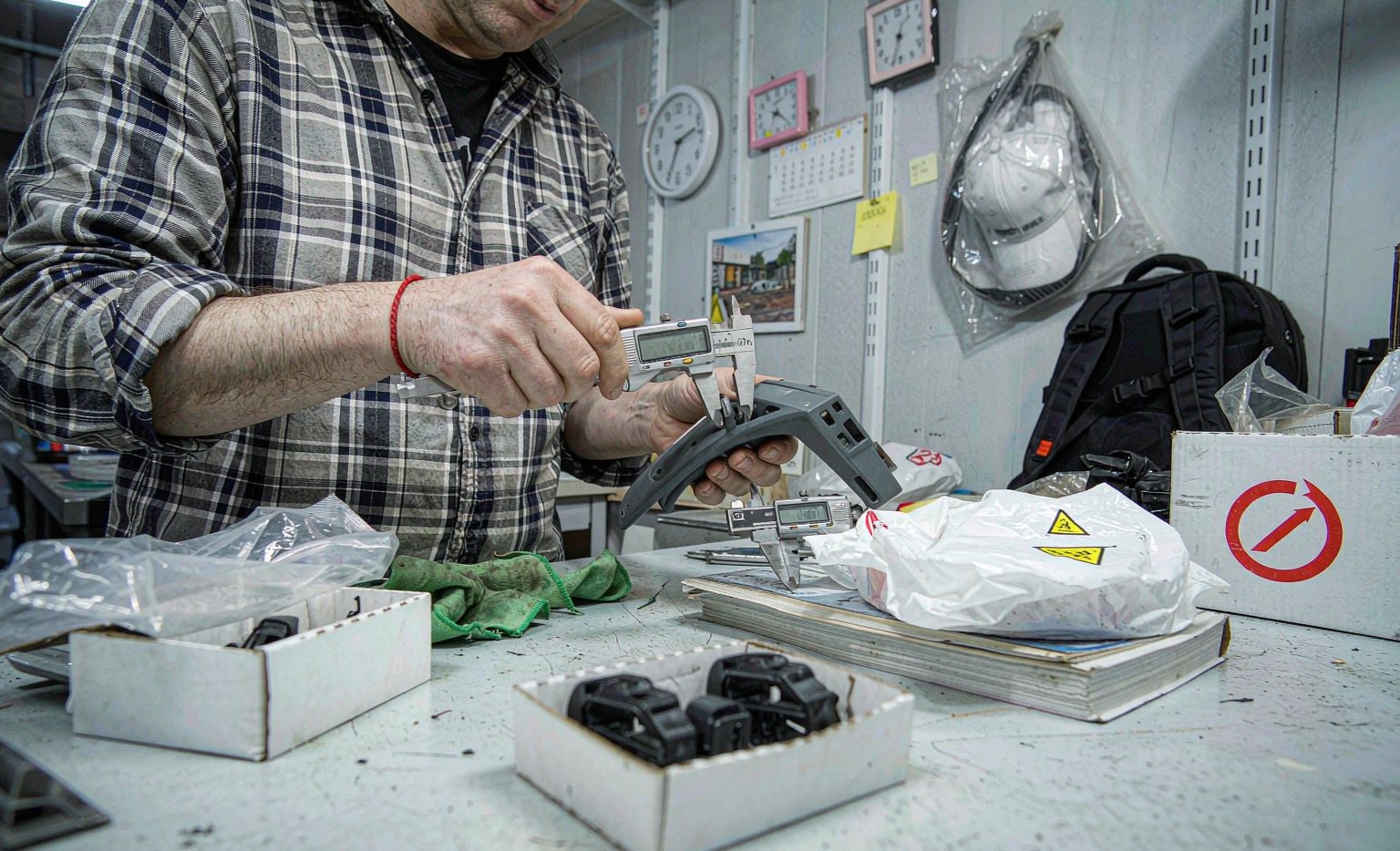
A tolerance is only meaningful if it can be measured and reproduced. For a critical dimension, ask the molder for a capability index (Cpk) from a first-article run: a Cpk above roughly 1.33 signals the process is comfortably inside the band, while a value near 1.0 means parts will regularly drift out. Measuring at the same temperature and conditioning state matters for hygroscopic resins.
Without a capability number, a tolerance is an aspiration rather than a specification, and the first audit will expose the difference.