




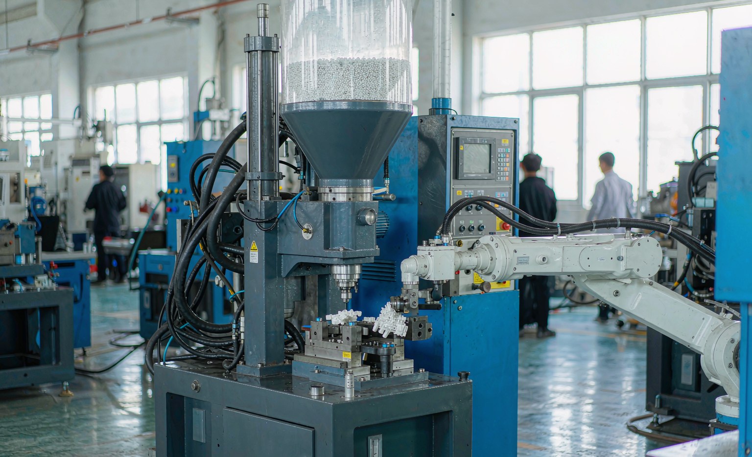
Đúc nhựa phun áp lực Biến các hạt nhựa nhiệt dẻo thành các bộ dạng net-shape bằng cách nung chảy nhựa và phun nó dưới áp lực vào khuôn thép chính xác. Đây là quy trình phổ biến nhất cho các thành phần nhựa sản xuất số lượng lớn, vì mỗi chu kỳ tạo ra một bộ phận giống hệt nhau với dung sai chặt chẽ và hoàn thiện bề mặt chất lượng cao. Hướng dẫn này bao gồm quy trình, lựa chọn vật liệu, kích thước máy, các quy tắc thiết kế cho khả năng chế tạo (DFM), các khiếm khuyết phổ biến, thời gian gia công khuôn và cách tìm nguồn cung cấp sản xuất OEM/ODM.
Quy trình đúc phun, từng bước
Mỗi chu kỳ lặp lại năm giai đoạn:
- Kẹp — khuôn đóng và đơn vị kẹp áp dụng toàn bộ lực tonnage, giữ chặt lòng khuôn và lõi lại với nhau chống lại áp lực phun.
- Bơm — trục vít đi giật nảy đẩy “bùn” nóng chảy qua cổng phun và kênh dẫn vào lòng khuôn. Quá trình phun thường mất 0,5–5 giây.
- Trữ (hold) — áp suất thấp hơn bù lại độ co ngót khi bộ phận làm lạnh, ngăn ngừa vết lún (3–15 giây).
- Làm nguội — bộ phận bị đông cứng; làm lạnh thường chiếm 50–70% thời gian chu kỳ tổng thể (5–40 giây, phụ thuộc vào độ dày của thành).
- Đẩy ra — khuôn mở và các chốt đẩy đẩy bộ phận hoàn thiện ra ngoài (1–3 giây).
Quy trình được mô tả từ Kiến thức về chất dẻo và Nhựa LSY.
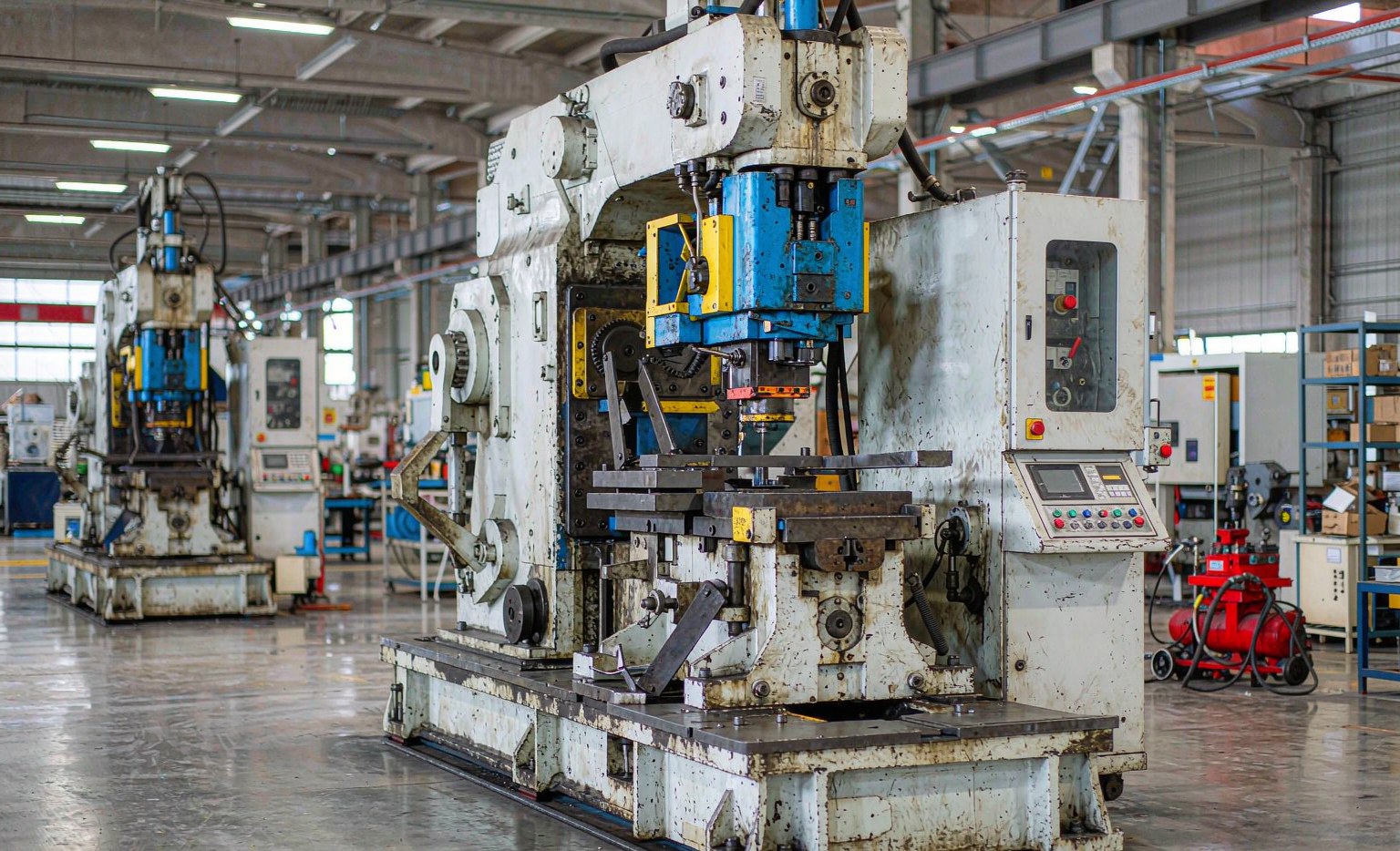
Lựa chọn nhựa phù hợp: nhiệt độ nóng chảy, nhiệt độ khuôn và độ co ngót
Việc lựa chọn vật liệu quyết định hiệu suất cơ học, hoàn thiện bề mặt và độ chính xác kích thước. Bảng dưới đây liệt kê các cửa sổ gia công và độ co ngót điển hình — những giá trị mà kỹ sư sử dụng để xác định kích thước bộ phận và khuôn.
| Polyme | Nhiệt độ nóng chảy (°C) | Nhiệt độ khuôn (°C) | Độ co ngót (%) |
|---|---|---|---|
| PE-HD | 200–280 | 20–50 | 1.5–3.0 |
| PP | 200–270 | 20–80 | 1.0–2.5 |
| ABS | 220–270 | 50–80 | 0.4–0.7 |
| PA 6 | 230–280 | 60–100 | 0.5–1.5 |
| PA 66 | 270–305 | 80–110 | 0.8–2.0 |
| PC | 280–320 | 80–110 | 0.5–0.7 |
| POM | 180–215 | 60–120 | 1.5–2.5 |
| PEEK | 370–400 | 170–200 | 1.0–1.4 |
Common production materials also include PC for transparent, impact-resistant parts and TPE/TPR for soft-touch overmolding. Data from KunststoffWissen material tables.
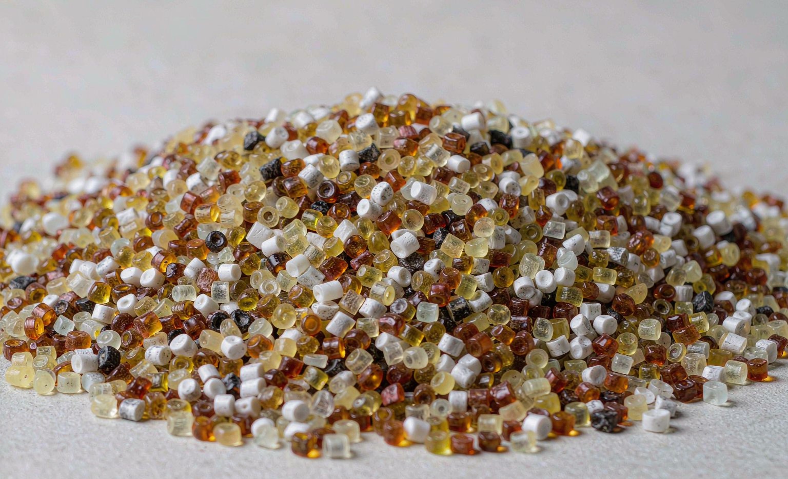
Machine sizing: clamping force and shot weight
Correct tonnage prevents flash (excess pressure pushing plastic out of the mold) without over-clamping. The required clamping force is:
F = A × p × S
where A is the projected area (cm²), p the cavity pressure (bar) and S a safety factor of 1.15–1.30. For example, a 200 cm² projected area at 500 bar with S = 1.2 needs F = 1,200 kN ≈ 122 metric tons. Injection pressure itself typically runs 800–2,500 bar. As a rule, shot weight should be 20–80% of barrel capacity to keep residence time in range (Kiến thức về chất dẻo).
Machine sizes span roughly 90 T to 1,200 T for typical moulding shops, up to 2,500 T for large parts; shot volumes from ~10 g to 2,500 g. Tolerances commonly hold ±0.05 mm, with tighter control (down to ±0.02 mm) achievable by compensating resin shrinkage (Trumax).
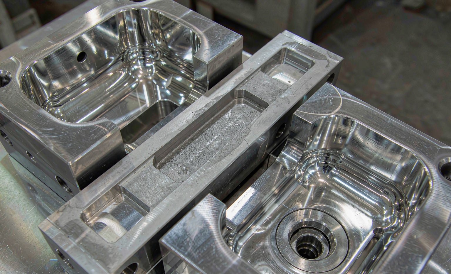
Design for manufacturability (DFM)
Molding success is decided at the design stage. Key rules:
- Uniform wall thickness — variations cause sink marks and warpage; aim for consistent thickness for even cooling.
- Draft angles — a minimum of 1°–2° on vertical walls for clean ejection without scuffing.
- Gate location — strategic placement optimises fill and minimises weld lines that weaken the part.
- Venting — release trapped air to avoid burn marks and short shots.
- Cooling channels — uniform layout (temperature within ±2 °C) reduces warpage and shortens cycle time.
Mold-flow simulation (e.g. CAE/Moldflow analysis) validates fill and cooling before the tool is cut (ABIS Mold).
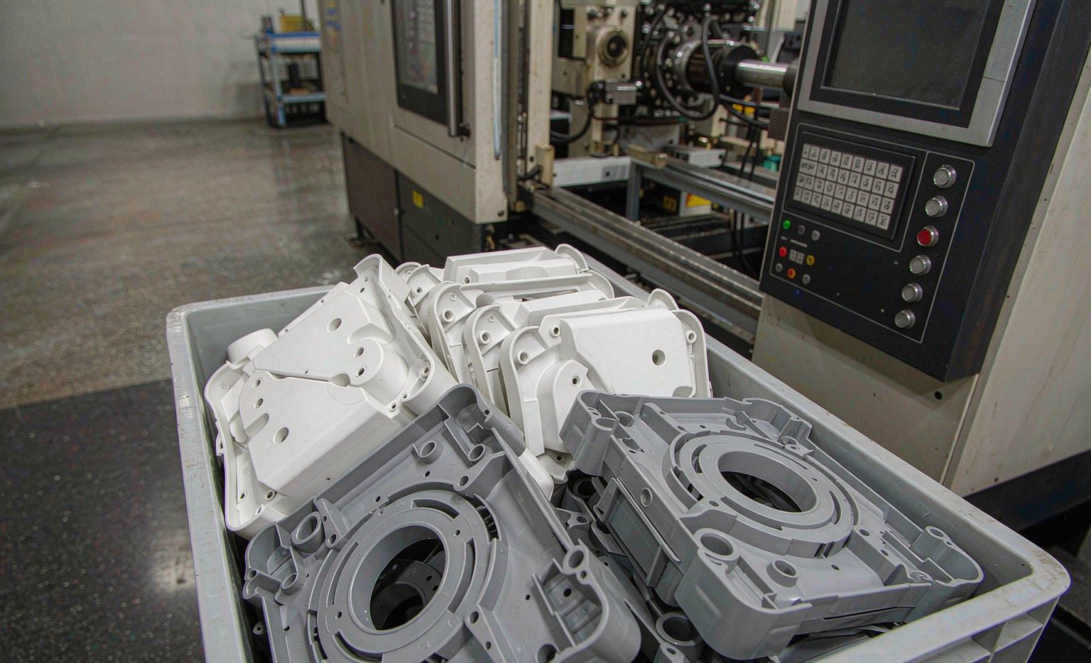
Common defects and how to fix them
| Defect | Common cause | Fix |
|---|---|---|
| Vết lõm | Insufficient holding pressure/time | Increase pack pressure and time |
| Short shot | Low melt temperature, slow injection | Raise melt temperature, increase injection speed |
| Flash | Excessive injection pressure / worn mold | Reduce pack pressure, verify clamping force |
| Silver streaks | Wet material or burned polymer | Dry resin properly; reduce melt temperature |
| Warpage | Uneven cooling or post-shrinkage | Balance cooling channels, extend cooling time |
| Burn marks | Trapped air at the flow front | Add venting, slow injection near end of fill |
Advanced capabilities: insert and overmolding
Beyond single-material parts, two techniques solve assembly and ergonomics problems:
- Insert molding — a metal insert (threaded boss, electrical contact) is placed in the mold before injection, so the plastic flows around it to form one bonded unit. This eliminates secondary assembly and increases strength.
- Overmolding — a rigid substrate (e.g. PP) is combined with a soft-touch material (TPE/TPR) to create grips, seals and handles with a structural core.
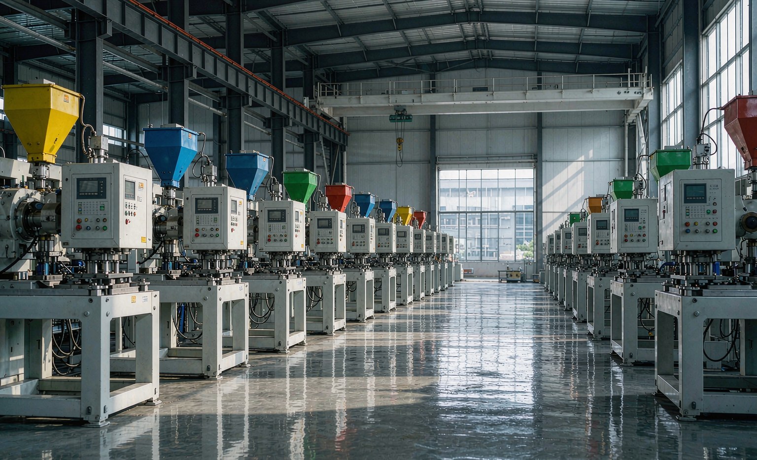
Tooling, lead time and sourcing OEM plastic parts
- Tooling lead time — standard molds take 15–30 days; complex, multi-cavity or side-action molds 30–60 days. An in-house mold workshop shortens turnaround versus outsourced tooling.
- MOQ — standard parts often 100–500 units; custom OEM projects depend on mold complexity and material.
- Materials — virgin resin for food-grade and ESD applications; recycled PP/HDPE acceptable for non-food-grade.
- Certifications — look for ISO 9001, and FDA / UL94 V0 where relevant (medical, flame-retardant electronics).
- Cycle economics — cycle times from 15–120 s; thin-wall packaging can run under 5 s. Cooling efficiency is the biggest lever on unit cost.
Internal resources
DAYIN is a plastic injection molding and OEM/ODM manufacturer with 30+ years’ experience, 100+ machines and plants in China and Vietnam, offering mold design, molding and assembly. Related capabilities: