



射出成型模具製造解析:流程、設計與應用

本注塑模具製造指南涵蓋了從逐步流程到專家設計技巧、材料、應用及關鍵常見問題的所有內容。.

注射模具製造:它是什麼以及它是如何工作的?

對於要求品質與效率的產業而言,注塑模具製造不可或缺,範圍涵蓋汽車、電子及消費性產品。這種普及性反映在市場的大幅成長上。根據 大視野研究, ,全球注塑成型塑膠市場在 2023 年的估值估計為 $330.41 十億美元,預計從 2024 年到 2030 年將以 3.4% 的複合年增長率(CAGR)擴張。.

因此,本文將深入探討注塑成型的運作原理、所使用的材料以及關鍵的設計考量,以提供這項重要製造技術的全面概覽。.

目錄:
1. 什麼是塑膠注塑成型?為何它如此受歡迎?

2. 塑膠注塑成型如何運作:塑膠注塑成型過程的 5 個關鍵步驟

3. 注塑成型設計應考慮哪些事項?

4. 塑膠注塑成型使用的材料

5. 注塑成型的表面處理選項

6. 塑膠注塑成型的常見應用

7. DAYIN 的專家級客製化塑膠注塑成型服務

8. 關於注塑模具製造的常見問題

什麼是塑膠注塑成型?為何它如此受歡迎?

注塑成型是一種製造工藝,涉及將材料加熱至熔化狀態,然後在壓力下注入客製化設計的模具中進行量產。隨後,熔融材料冷卻並固化成與模具完全相同的形狀,從而產生細節豐富的產品。.

雖然塑膠是最常用的材料,但此工藝也可應用於金屬、玻璃和橡膠。這種 多樣且廣泛的材料選擇 是注塑成型受歡迎的主要原因之一,因為製造商會針對其特定專案進行調整。.

該工藝也以能創造 高度精確的設計而聞名,即使是複雜的形狀, ,每個零件都能符合嚴格的公差標準。這些 均勻且高品質的零件 通常 需要很少或不需要後續加工, ,從而降低了勞動成本和生產時間。.

此外,注塑成型透過模具保持了 產品的一致性 ,適用於 大規模製造 。由於初始模具製作完成後,單件成本顯著下降,因此它甚至 在量產中具有成本效益 。這些優勢共同促進了注塑成型在眾多行業中的廣泛採用。.

塑膠注塑成型如何運作:塑膠注塑成型過程的 5 個關鍵步驟

本節將提供塑膠注塑成型過程的詳細逐步說明,分解每個關鍵階段以便清晰理解。.

步驟 1:模具的設計與製造

在任何零件生產之前,必須仔細設計和製造模具本身,因為它為整個注塑成型過程奠定了基礎。.

此模具作為最終零件的負像印模,決定其形狀、表面處理和結構完整性。它由兩個主要部分組成:A側(型腔)和B側(型芯)。 A側 是外觀面,通常具有為美觀而設計的可見表面特徵。 B側 是功能面,包含對零件強度和組裝至關重要的結構元素,如加強筋、卡扣和螺柱。.

通過利用先進的計算機輔助設計(CAD)軟件,工程師可以為兩側創建詳細的注塑模具設計3D模型,以確保準確性、優化材料流動並最大限度地減少生產缺陷。.

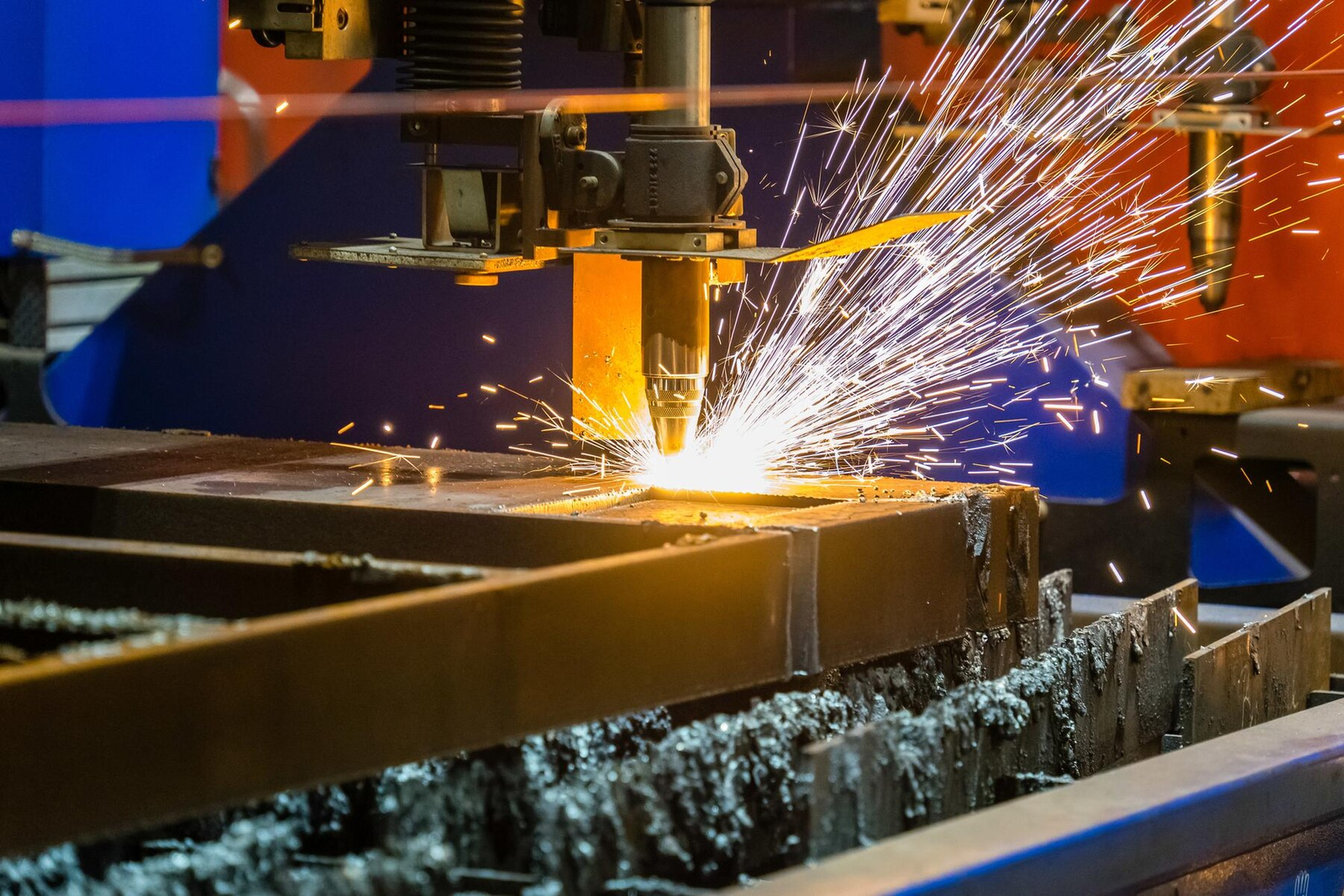
設計定稿後,可通過CNC加工、電火花加工(EDM)或3D打印等注塑模具製造工藝進行製造。.

Injection molds can be produced through CNC machining, EDM, or 3D printing.
來源: Freepik

標準計算機數控(CNC)加工 

CNC加工是生產高精度模具最常見的方法。在預編程軟件的控制下,CNC銑床和車床將鋁或工具鋼塊切割成所需設計,精度極高。這種方法靈活多變,能夠生產各種形狀。.

電火花加工(EDM) 

在EDM中,石墨或銅電極放電產生電火花來侵蝕金屬表面,從而實現高度詳細的型腔和精細的表面處理。EDM特別適用於加工硬化鋼以及生產傳統加工難以或無法實現的形狀。.

3D打印 

雖然傳統上不用於最終的大規模生產模具,但3D打印已成為原型製作和小批量製造的可行選擇。這種增材製造技術可以快速從專用樹脂或金屬生產模具,縮短小批量生產的交貨時間和成本。.

步驟2:熔化熱塑性塑料顆粒

From this point forward, the process will take place within the injection molding machine itself.

The injection molding machine will melt the thermoplastic pellet, feed it into the mold cavity, and release the final part once it solidifies after cooling.

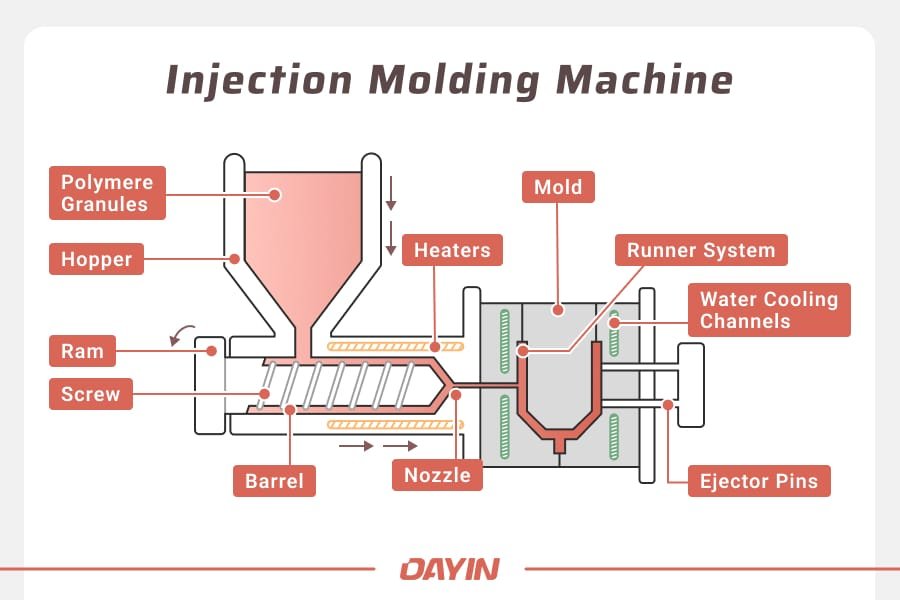
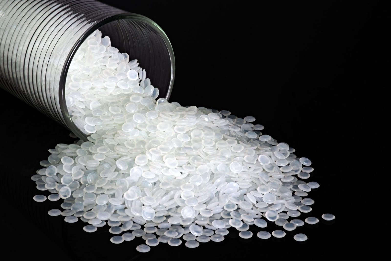
At this stage, solid plastic pellets will be transformed into a molten state for injection. The raw thermoplastic material — either virgin resin or recycled plastic — is first loaded into a hopper positioned at the top of the machine. If necessary, additives such as color pigments or reinforcing agents are mixed in together as well.

From the hopper, these plastic pellets are gradually dispensed into the barrel of the machine, where a screw mechanism rotates to transport and heat the material through friction. At the same time, external heating elements surrounding the barrel steadily raise the temperature of the thermoplastic until it is fully melted.

Maintaining precise temperature control is critical in this step, as it directly impacts the molten material’s viscosity and flow characteristics, ultimately influencing the quality and accuracy of the final molded parts.

Step 3: Injecting Molten Plastic into the Mold

Once the thermoplastic material reaches a molten state, the machine injects the molten plastic using a ram while the nozzle maintains high pressure. This forces the material through the sprue, the main channel into the mold. From there, the material travels through the runner system, distributing the plastic evenly. Then, the material enters the mold cavity through the gate — the narrow opening that controls the final flow rate.

To ensure the molten plastic fills the mold completely and forms a precise shape, the mold halves must be held together with significant clamp pressure to prevent material leakage. Nevertheless, proper balancing between injection pressure and clamp pressure is crucial; too little force can result in incomplete parts, while excessive force may damage the mold or affect part quality.

Step 4: Holding and Cooling the Plastic Part

After the molten plastic is injected into the mold, it undergoes a critical phase known as the “holding time”. During this period, the material is kept under sustained pressure to ensure it fully occupies the mold cavity and compensates for any shrinkage that may occur as it cools. The specific duration for this phase varies depending on the type of thermoplastic used and the complexity of the part, ranging from milliseconds to several minutes.

Once the holding time is over, the pressure is released. Consequently, the part is left to cool and harden within the mold, taking its final shape. The cooling time is also carefully controlled to prevent defects such as warping or sink marks. As such, many molds include built-in cooling channels to speed up this process by circulating water or other cooling fluids.

Step 5: Ejecting the Plastic Part

Now that the plastic part has fully cooled and solidified, the mold opens while ejector pins push the part out of the mold cavity. This ejector mechanism ensures smooth removal without damaging the part’s structure.

The ejected parts typically drop into a collection bin or onto a conveyor belt for further processing. While the part is essentially complete in this form, it may require post-processing, such as surface finishing, excess material trimming, or assembly before packaging and distribution. This final phase ensures that the injection-molded parts meet the desired specifications before being sent for commercial or industrial use.

3. What Should be Considered for Injection Molding Designs?

Injection molding, while highly versatile, is susceptible to various defects if design parameters are not carefully adjusted. Common issues include warping, sink marks, drag marks, knit lines, and short shots:

  • Warping occurs when different sections of a part cool and shrink at varying rates, leading to bending.
  • Sink marks are small depressions on the surface caused by uneven cooling, often in thick sections.
  • Drag marks result from the part scraping against the mold during ejection, typically due to insufficient draft.
  • Knit lines are visible lines where two flow fronts of molten plastic meet, potentially weakening the part.
  • Short shots occur when the mold cavity is not completely filled, resulting in an incomplete part.

By implementing the following best practices in areas like tolerances, wall thickness, core geometry, and more, manufacturers can minimize these defects and produce high-quality parts:

3.1. Tolerances

Injection molding allows for precise manufacturing, but designers must account for material shrinkage and process variations. Standard tolerances typically fall around ±0.003 inches (±0.076 mm), though tighter tolerances as low as ±0.001 inches (±0.025 mm) can be achieved. However, stricter tolerances increase production costs due to additional tooling adjustments and quality control measures. For small production runs, secondary machining processes like drilling or reaming may be more cost-effective for achieving precise fits.

Furthermore, material selection also impacts tolerance consistency. For example, rigid resins like ABS and polycarbonate exhibit minimal shrinkage, while flexible thermoplastics such as TPE have greater variation. Thus, designers must balance the need for accurate tolerance and the desired part flexibility when choosing the material.

3.2. Wall Thickness

Ideally, injection molding designs should aim for uniform wall thickness throughout the part. Sudden changes in thickness can create internal stresses, leading to deformation or weak points in the final product. Additionally, excessively thick walls can trap heat, increasing cooling time and affecting dimensional stability.

A general guideline is to keep wall thickness within the recommended range for the chosen resin — typically between 1.2mm and 3mm for most materials. When variations are unavoidable, transitions should be gradual, utilizing chamfers or fillets to ensure smooth material flow and even cooling. For optimal results, transition lengths should be approximately 3 times the difference in thickness between sections.

3.3. Core Geometry

Optimizing core geometry in injection molding involves hollowing out thick sections to minimize material usage and prevent defects. Designers can also support the hollow sections using ribs to maintain strength and stiffness while keeping wall thickness within recommended limits.

For the best results, ribs should be designed with a thickness no greater than 50% of the main wall thickness and a height no more than 3 times their thickness to ensure stability without introducing sink marks. Moreover, using a base fillet radius greater than 1/4 of the rib thickness helps improve stress distribution and material flow.

With a properly designed core, the part integrity can be enhanced while reducing cooling time, lowering production costs, and improving overall manufacturability.

3.4. Corner/Edges

Sharp corners and edges should be avoided as they create stress concentrations that weaken the part. To minimize this issue, round all part edges with fillets. For interior corners, use a radius of at least 0.5 times the wall thickness. Exterior corners should also have a radius equal to the interior radius plus the wall thickness. These design practices for corners and edges help ensure consistent material distribution.

3.5. Draft Angles

Draft angles are essential in injection molding to ensure smooth part ejection. Without a proper draft, vertical walls may scrape against the mold during release, potentially damaging the part’s surface and increasing wear on the tooling.

It is usually best to apply a minimum draft angle of 2° on all vertical features, though taller features (above 50 mm) should have an additional 1° for every 25 mm in height. Textured surfaces require even more draft—typically 1° to 2° extra—to accommodate the deeper texture and avoid sticking. On top of that, ribs and other thin features should include draft angles to facilitate ejection without compromising structural integrity.

3.6. Undercuts

Undercuts in injection molding can create challenges during mold opening and part ejection, as material obstructs the straight-pull action of a standard two-part mold. To accommodate undercuts without significantly increasing complexity or cost, designers can apply several strategies.

One approach is to eliminate undercuts by redesigning the part with shutoffs, which can be used to remove material in problematic areas, such as internal snap-fits or side holes, preventing the need for complex tooling. Another method is repositioning the parting line to align with the undercut, allowing the mold to open naturally without obstructions.

For flexible materials like polypropylene (PP) or nylon (PA), stripping undercuts (bumpoffs) may be viable. This technique relies on the material’s ability to stretch and deform over the mold before returning to its original shape. However, it requires a lead angle of 30° to 45° and is not recommended for rigid or fiber-reinforced plastics.

When undercuts cannot be avoided, side-action mechanisms or lifters provide a solution. These moving components slide into place as the mold closes and retracts before ejection, freeing the trapped feature. Side actions should be designed to move at a 90° angle for efficiency and must have enough clearance for movement.

By carefully selecting the right approach for undercuts, designers can streamline the manufacturing process for injection molding.

3.7. Fastening Elements

Injection-molded parts often require fastening features for assembly and functionality. Common fastening elements include bosses, threaded inserts, snap-fit joints, and living hinges.

Here’s how you can design them to improve part performance while maintaining manufacturability:

Bosses

Bosses are cylindrical protrusions designed to receive screws, inserts, or other fasteners. They should have an outer diameter at least twice the nominal diameter of the screw or insert, with a core hole extending to the base to maintain uniform wall thickness. Nonetheless, bosses should be kept separated from thick walls to prevent sink marks.

Bosses can also be reinforced with ribs or connections at nearby walls to prevent weak points and deformation during injection molding. Adding a slight chamfer at the entrance of the bosses can even improve fastener insertion.

Threads 

While some designers may mold threads directly into the parts, this method often complicates the production process due to undercuts. On the other hand, threaded inserts can be installed using thermal, ultrasonic, or in-mold insertion, providing an alternate attachment point that is just as durable.

Whether molded threads or inserts are used, it is best to include 0.8 mm relief at thread edges to prevent stress buildup. Also, they should be designed with trapezoidal or buttress threads for added strength.

Snap-Fit Joints

Snap-fit joints provide tool-free, reusable assembly options. They rely on flexible arms that snap into place, making them ideal for enclosures, battery compartments, and covers. Still, fit joints are a type of undercut so remember to design them with the tips mentioned earlier.

To elaborate, cantilever snap-fits are the most common type and should be designed with draft angles to facilitate easier part ejection and assembly, especially when there are vertical walls. Adjust their width and length, while ensuring the thickness exceeds 0.5 times the main wall thickness to control deflection and retention force.

Living Hinges

Living hinges are thin, flexible sections connecting two parts, commonly used in containers and lids. They must be made from ductile materials like polypropylene (PP), polyethylene (PE), or Polyamide (PA)  to withstand repeated flexing.

For better durability, make sure to design hinge thickness between 0.20 mm to 0.35 mm and split hinges (>150 mm) into multiple segments. Furthermore, adding fillets and shoulders can help ensure smooth material flow and reduce stress concentrations.

3.8. Text and Symbols

Instead of adhesive or painted decals, molded text and symbols may be used for logos, precautions, or other labels. When incorporating them into an injection-molded part, it is best to use embossed rather than engraved designs, as raised features are easier to machine into the mold and reduce production costs. The embossed text should also be at least 0.5 mm (0.020 inches) high to ensure clarity and legibility.

For the font, sans-serif designs with uniform stroke widths, such as Arial, Verdana, or Century Gothic Bold, improve readability and consistency. A minimum font size of 20 points is recommended to prevent loss of detail during molding. Additionally, text should be aligned perpendicular to the parting line to avoid distortion. These guidelines help prevent excessive mold wear and ensure clear, crisp lettering on the final product for a professional appearance.

4. Materials Used in Plastic Injection Molding

This section explores both mold materials and the diverse resins used to create injection-molded products.

4.1. Common Materials for the Plastic Injection Mold

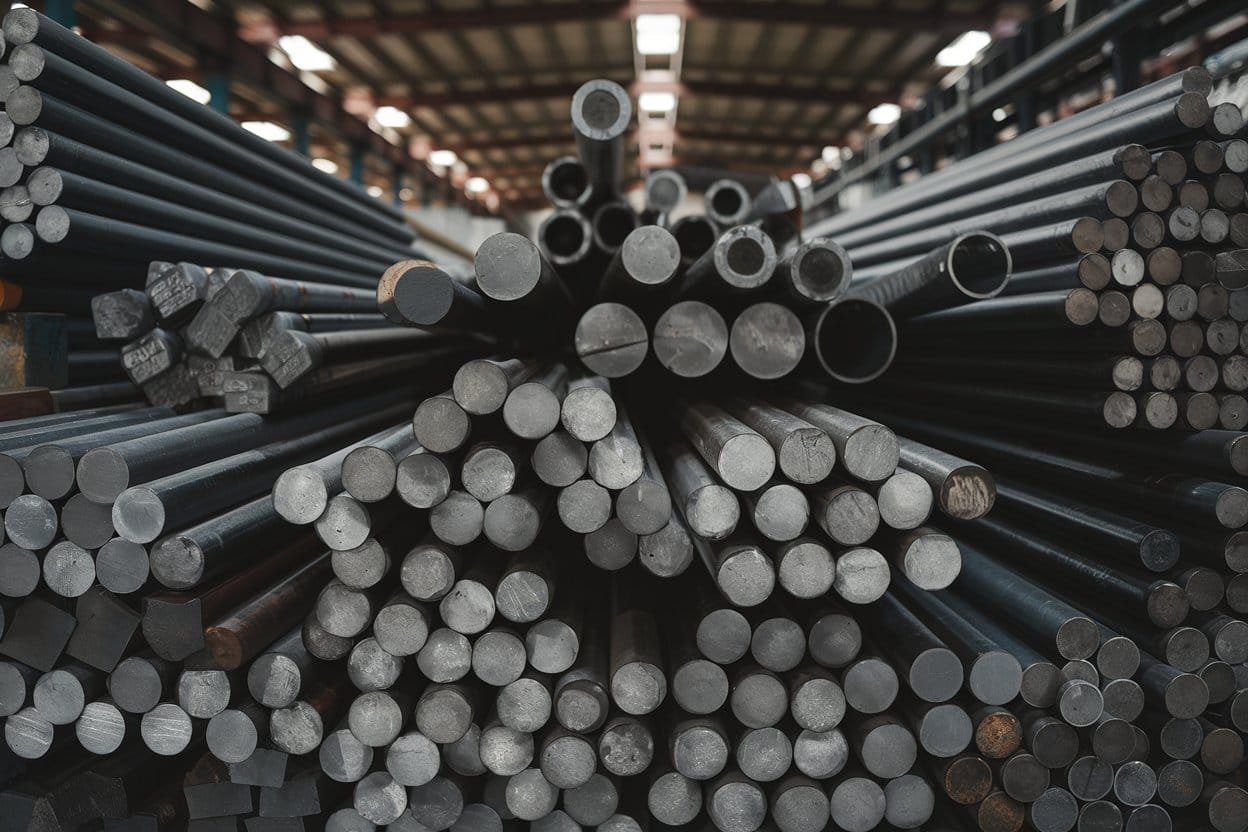
Injection molds are typically made from steel, aluminum, or beryllium-copper alloy.

Common materials for the plastic injection mold include steel, aluminum, and beryllium-copper alloy.

Steel molds, particularly those made from hardened or pre-hardened steel, are highly durable and ideal for high-volume production. Hardened steel molds undergo heat treatment, making them exceptionally wear-resistant and capable of producing over a million parts. Pre-hardened steel molds, while less resistant to wear, provide a cost-effective alternative for moderate production volumes.

Aluminum molds are a more affordable option and are well-suited for lower-volume production runs. Although they lack the durability of steel molds, they offer excellent thermal conductivity, which helps reduce cycle times. With proper machining, aluminum molds can produce tens of thousands to hundreds of thousands of parts efficiently.

While less common, beryllium-copper alloys may be used in mold inserts to enhance heat dissipation in areas requiring rapid cooling.

4.2. Resin Materials for the Injection-Molded Product

Injection molding uses different thermoplastic resins to achieve the required mechanical properties and chemical resistance, ensuring optimal performance for the intended use.

Thermoplastic resins are used to make injection-molded products.

Common resin material options include:

  • Acrylonitrile Butadiene Styrene (ABS): It is a versatile and cost-effective material known for its strength, toughness, and ease of processing, making it popular in consumer goods and automotive parts.
  • Acetal (POM): It is also known as polyoxymethylene and provides high strength, low friction, and excellent wear resistance, making it ideal for gears and mechanical components.
  • Liquid Crystal Polymer (LCP): It exhibits high strength, superior flow properties, and thermal stability, making it well-suited for thin-walled electronic components.
  • Nylon (Polyamide, PA): This is a strong, wear-resistant material often used in high-performance applications, though it can be prone to moisture absorption and warping.
  • Polycarbonate (PC): It is a durable, impact-resistant plastic with good optical clarity, frequently used for safety glasses, electronic housings, and automotive components.
  • Acrylic (PMMA): Commonly known as Plexiglas, this is a transparent material with excellent optical properties but is more brittle compared to other plastics.
  • Polypropylene (PP): It is widely used as a commodity resin due to its affordability, fatigue resistance, and flexibility, making it ideal for packaging, containers, and living hinges.
  • Polyethylene (PE): This is another cost-effective material available in high-density (HDPE) and low-density (LDPE) forms, offering excellent chemical resistance and impact strength.
  • Polystyrene (PS): This is a rigid, inexpensive plastic often used in packaging and disposable products.
  • Polyurethane (PU): It is known for its flexibility, durability, and resistance to abrasion, commonly used in cushioning applications and industrial components.

5. Surface Finishing Options for Injection Molding

Injection-molded parts typically do not require post-processing, as they achieve a fine surface finish directly from the mold. However, surface finishes can enhance both aesthetics and functionality.

A well-chosen surface finish can provide visual appeal, making the product look more refined or high-end. It can also enhance functionality by reducing friction, improving wear resistance, or adding grip to certain components. Additionally, textures can help mask minor defects such as flow lines or sink marks, ensuring a more uniform appearance.

Here’s a summary of common surface finishes, as well as a description of as-machined parts for comparison:

Finish Description *SPI Standards Applications
Glossy The mold is polished with a diamond buff to create a mirror-like surface. A-1
A-2
A-3
Parts requiring the smoothest surface, including high-end consumer products, optical lenses, and parts requiring a reflective look.
Semi-Gloss The mold is polished with fine-grit sandpaper, producing a smooth but less reflective surface. B-1
B-2
B-3
Used for parts requiring a sleek appearance without a full glossy effect, such as electronic casings.
Matte Fine stone powder is used to remove machining marks, creating a soft, low-gloss surface. C-1
C-2
C-3
Suitable for parts where aesthetics are not critical but smoothness is needed, such as mechanical housings.
Textured The mold is first polished with stone powder and then sandblasted for a rougher, textured surface. D-1
D-2
D-3
Often used for grip-enhanced surfaces, automotive interiors, or to mask minor defects.
As-Machined The mold is finished with no additional polishing. The tool marks may be visible. N/A Non-cosmetic parts, such as internal, industrial, or hidden components where finish quality is not a concern.

*Note: The Society of Plastics Industry (SPI) standards provide a system that specifies surface finishes on injection molds, categorizing finishes from highly polished (A-grade) to textured (D-grade), with numerical sub-grades to indicate finer levels within each category.

6. Common Applications of Plastic Injection Molding

Injection molding satisfies diverse product needs across various industries:

6.1. Automotive 

In the automotive industry, injection molding is used to manufacture essential interior and exterior components, as it offers accuracy to help meet stringent industry requirements.

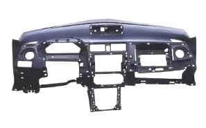
DAYIN leverages injection molding to produce automotive parts like car dashboards that meet stringent industry requirements.

For instance, 大銀 relies on this technique to produce car dashboards designed for high precision, heat resistance, and impact durability. Other commonly injection-molded automotive parts include bumpers, door panels, and trim components.

6.2. Home Appliances 

For household appliances, injection molding ensures the production of durable and aesthetically refined plastic components, from washing machine panels to refrigerator compartments.

DAYIN creates robotic vacuum cleaner housings with injection molding, providing high precision and impact resistance while maintaining an appealing finish.

Manufacturers like DAYIN also create 机器真空吸尘器 housings with this process, providing high precision and impact resistance while maintaining an appealing finish.

6.3. Telecommunications 

Due to the consistency in mass production, the telecommunication industry uses injection molding to create electronic components, such as the keyboard housings and keycaps by DAYIN which are highly precise and durable.

DAYIN uses injection molding to create electronic components like keyboard housings and keycaps for consistency and durability.

Many plastic enclosures for consumer electronics, such as phone cases and router casings, are also injection-molded.

6.4. Consumer Products 

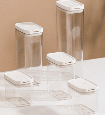
Injection molding is widely used to create everyday items from toys to food packaging, and more. As an example, DAYIN offers injection-molded airtight containers with excellent durability and food-grade safety, making them ideal for food and beverage storage.

DAYIN offers injection-molded airtight containers that are food-grade safe.

Additionally, their dishware produced through injection molding also offers a lightweight yet robust solution with an appealing design.

DAYIN’s injection-molded dishware offers a lightweight yet robust solution with an appealing design.

7. Expert Custom Plastic Injection Molding Services at DAYIN

Choosing the right injection molding manufacturer is essential for producing high-quality, reliable products. DAYIN is a leading expert in custom plastic injection molding, offering comprehensive, all-in-one services, including mold design and manufacturing, injection molding, electronic assembly, secondary processing, and rigorous quality inspection. Whether you need ODM/OEM solutions or fully customized manufacturing, DAYIN provides seamless production from start to finish.

By relying on scientific injection molding techniques such as mold flow analysis and real-time parameter monitoring, DAYIN ensures a more stable and efficient production process, minimizing the risks of plastic part defects or deformations.

With dual production facilities in Dongguan, China, and Bac Ninh, Vietnam, DAYIN also offers flexible and competitive manufacturing solutions. This can be a strategic advantage, reducing the impact of tariffs for US-bound products and ensuring stable supply chain operations.

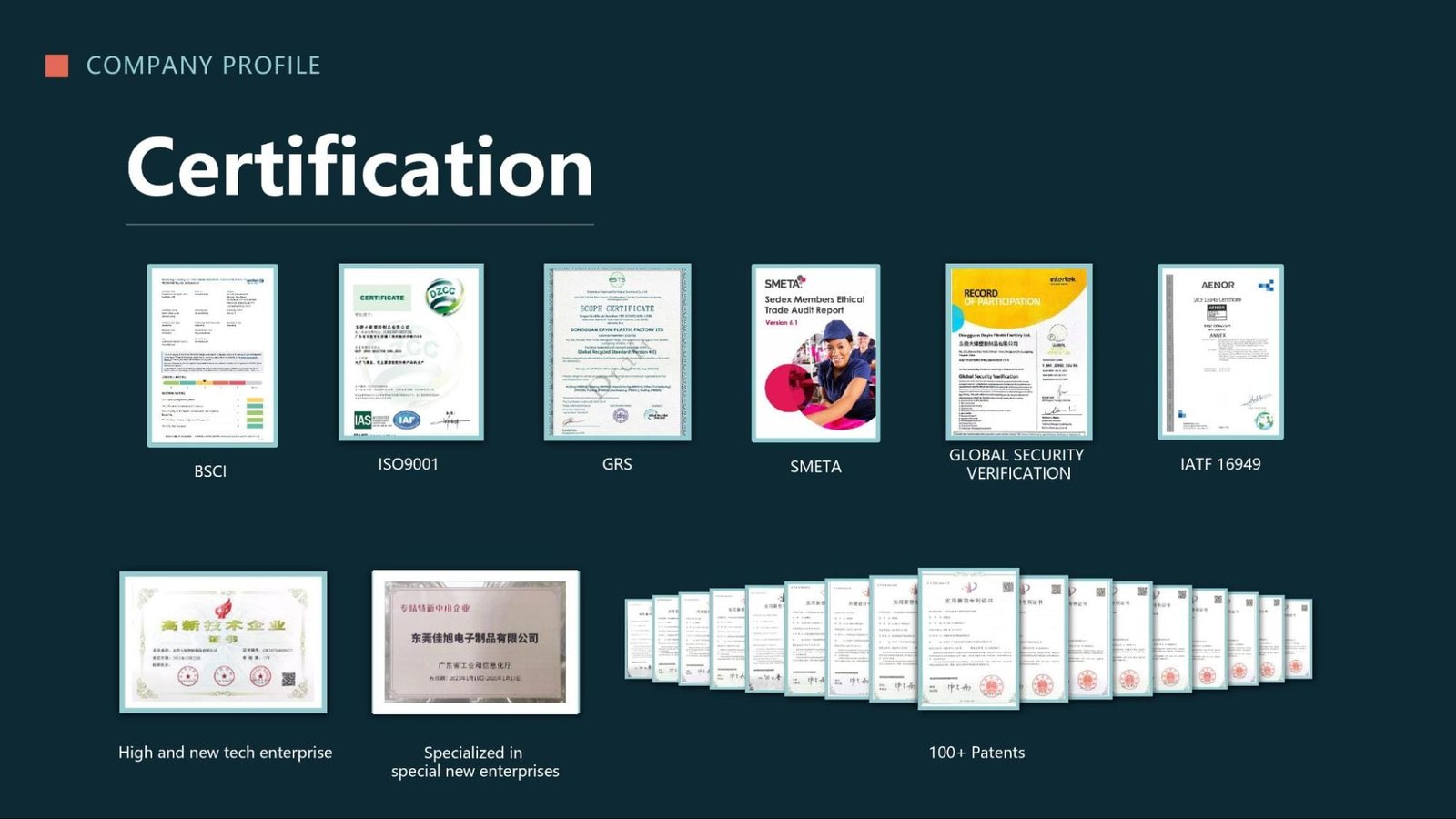
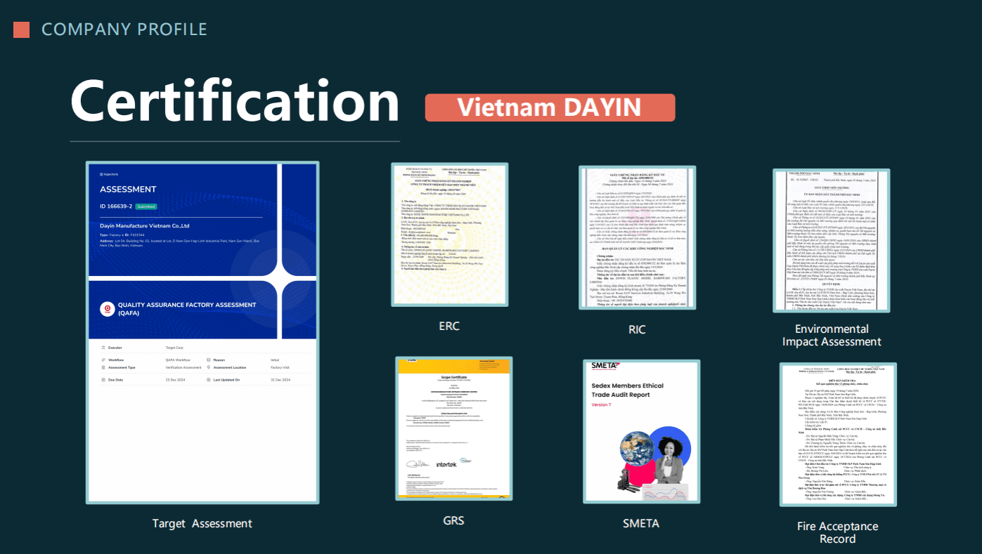
Moreover, DAYIN maintains strict 品質管理 and complies with international standards. The China facility is ISO9001, SCAN, SGS, BSCI, GRS, SMETA, and IATF 16949 certified, while the Vietnam facility is the only one within the nation to hold the exclusive Target QAFA certification, along with ERC, RIC, and environmental compliance approvals.

International certifications and patents of DAYIN's plastic injection molded products from the China facility.

International certifications and patents of DAYIN's plastic injection molded products from the Vietnam facility.

Beyond these production capabilities, DAYIN excels in research and development (R&D) design for manufacturing (DFM) support, allowing clients to tailor design requirements to their specific needs while keeping up with the latest advancements. Currently, the facilities are even pioneering aluminum mold innovation for faster cycle times and maintenance, saving valuable time and providing more diversified choices for all collaborations.

Ready to experience exceptional custom plastic injection molding with expert service?
Contact DAYIN today to discuss your project needs.

聯繫我們


8. Frequently Asked Questions about Injection Mold Manufacturing

Q1. What are the disadvantages of plastic injection molding?

One of the primary limitations of plastic injection molding is that the tooling requires substantial start-up costs. Creating custom molds is expensive, making it less economical for small-volume runs. As such, modifications to the mold post-fabrication are costly too, often necessitating a new mold entirely.

Besides, compared to methods like 3D printing or CNC machining, injection molding has longer lead times, typically spanning several weeks for mold creation and production.

These factors should be carefully weighed when considering injection molding for a project.

Despite that, working with a manufacturer that offers design for manufacturability (DFM) support and prototyping services can help overcome these challenges. DFM ensures designs are optimized for molding, reducing costly revisions and boosting efficiency, while prototyping allows for design validation before committing to expensive tooling.

Q2. How much does it cost to make an injection mold?

Injection mold costs vary widely, ranging from $3,000 to $100,000+. This depends on factors like design complexity, the chosen mold material, and the required accuracy for the production run. Discuss your specific needs with an expert manufacturer to get a tailored quotation for the project.

Q3. How long does it take to manufacture parts with injection molding?

Typically, injection molding takes 6-10 weeks, with 4-6 weeks for mold development and 2-4 weeks for part production.

However, at DAYIN, our manufacturing expertise and advanced equipment allow us to offer a shorter production cycle, generally within 4-8 weeks.

Q4. How do manufacturers ensure the quality of injection-molded parts?

Manufacturers implement scientific molding to standardize the injection molding process, ensuring consistency across production runs. This involves defining and documenting optimal processing parameters, such as temperature, pressure, and cooling time, to achieve repeatable, high-quality results.

To verify quality, manufacturers also conduct a First Article Inspection (FAI), where initial samples are measured against design specifications. There are also industry-specific quality checks, such as the Production Part Approval Process (PPAP) for automotive that help guarantee defect-free parts.

In addition to that, manufacturers perform defect analysis through visual inspections, dimensional measurements, and material testing to detect issues such as warping, sink marks, or flash. Quality management systems, such as ISO 9001, further ensure compliance with strict industry standards.

Q5. Can I use additives for injection molding?

Yes, additives can be mixed with resin pellets during the injection molding process to enhance material properties and performance. Common options include:

  • Colorants: Used to achieve specific colors by mixing pigments with natural resin.
  • Carbon Fiber: Improves stiffness and strength while aiding in static dissipation.
  • Minerals (Talc, Clay): Act as fillers to reduce costs, increase hardness, and minimize warping.
  • PTFE (Teflon): Provides self-lubrication, making parts ideal for bearing applications.
  • Long Glass Fibers: Significantly increase strength and stiffness, though they can make molding difficult.
  • Aramid (Kevlar) Fibers: Offer reinforcement with less abrasion compared to glass fibers.
  • Glass Beads and Mica Flakes: Reduce warping and shrinkage by enhancing dimensional stability.
  • Stainless Steel Fibers: Help control electromagnetic (EMI) and radio frequency interference (RFI), often used in electronics.
  • UV Inhibitor: Protects plastics from degradation due to sunlight exposure, ideal for outdoor applications.

By selecting the right additives for injection molding, manufacturers can tailor plastic properties to meet specific mechanical, thermal, and aesthetic requirements.

Q6. What are the post-processing options for injection-molded parts?

To enhance functionality and aesthetics, injection-molded plastic parts can undergo various post-processing techniques, such as:

  • Welding: Ultrasonic welding uses high-frequency vibrations to generate heat, allowing plastic parts to be fused together or inserts to be embedded.
  • 雷射雕刻: A laser burns a permanent 2D image or text onto the plastic surface, ideal for branding and part identification.
  • Plastic Spraying: A coating is applied to enhance the appearance, texture, or durability of plastic components.
  • Hot Stamping: Uses heat and pressure to transfer metallic or pigmented foils onto plastic, often for logos or decorative elements.
  • Printing: Techniques like pad printing allow multi-color logos, instructions, or patterns to be applied at scale without affecting moldability.
  • Static Treatment: Applied to reduce static buildup, which is especially important for electronics and dust-sensitive applications.

DAYIN specializes in comprehensive secondary processing for plastic products, ensuring high quality for all customized injection-molded parts.